1、下面贴的是主函数,做的就是将串口1进行配置,配置成中断的方式然后while 1int main(void){ /* System Clocks Configuration */ RCC_Con熠硒勘唏figuration(); /* NVIC configuration */ NVIC_Configuration(); /* Configure the GPIO ports */ GPIO_Configuration(); USART_InitStructure.USART_BaudRate = 9600; USART_InitStructure.USART_WordLength = USART_WordLength_8b; USART_InitStructure.USART_StopBits = USART_StopBits_1; USART_InitStructure.USART_Parity = USART_Parity_No; USART_InitStructure.USART_HardwareFlowControl = USART_HardwareFlowControl_None; USART_InitStructure.USART_Mode = USART_Mode_Rx | USART_Mode_Tx; /* Configure USART1 */ USART_Init(USART1, &USART_InitStructure); /* Enable USART1 Receive and Transmit interrupts */ USART_ITConfig(USART1, USART_IT_RXNE, ENABLE); /* Enable the USART1 */ USART_Cmd(USART1, ENABLE); while (1) { }}
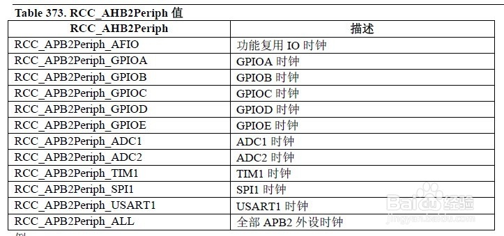
2、RCC的配置如下void RCC_Configuration(void){ SystemInit(); /* Enable USART1, GPIOA, GPIOx and AFIO clocks */ RCC_APB2PeriphClockCmd(RCC_APB2Periph_USART1 | RCC_APB2Periph_GPIOA| RCC_APB2Periph_AFIO, ENABLE);}串口1是PA9 PA10所以要打开RCC_APB2Periph_GPIOA用到串口1要打开RCC_APB2Periph_USART1串口1是复用功能要打开RCC_APB2Periph_AFIO
3、GPIO的设置void GPIO_Configuration(void){ GPIO_InitTypeDef GPIO_InitStructure; /* Configure USART1 Rx (PA.10) as input floating */ GPIO_InitStructure.GPIO_Pin = GPIO_Pin_10; GPIO_InitStructure.GPIO_Mode = GPIO_Mode_IN_FLOATING; GPIO_Init(GPIOA, &GPIO_InitStructure); /* Configure USART1 Tx (PA.09) as alternate function push-pull */ GPIO_InitStructure.GPIO_Pin = GPIO_Pin_9; GPIO_InitStructure.GPIO_Speed = GPIO_Speed_50MHz; GPIO_InitStructure.GPIO_Mode = GPIO_Mode_AF_PP; GPIO_Init(GPIOA, &GPIO_InitStructure);}只用到串口1 配置 PA9为输入因为是串口收 PA10为输出因为是串口发送

4、中断的配置void NVIC_Configuration(void){ NVIC_InitTypeDef NVIC_InitStructure; /* Configure the NVIC Preemption Priority Bits */ NVIC_PriorityGroupConfig(NVIC_PriorityGroup_0); /* Enable the USART1 Interrupt */ NVIC_InitStructure.NVIC_IRQChannel = USART1_IRQn; NVIC_InitStructure.NVIC_IRQChannelSubPriority = 0; NVIC_InitStructure.NVIC_IRQChannelCmd = ENABLE; NVIC_Init(&NVIC_InitStructure);}

5、串口中断的函数编写 stm32f10x_it.c文件中void USART1_IRQHandler(void){ if(USART_GetITStatus(USART1, USART_IT_RXNE) != RESET) { /* Read one byte from the receive data register */ RxBuffer1[0] = USART_ReceiveData(USART1); if(USART_GetITStatus(USART1, USART_IT_TXE) == RESET) { USART_SendData(USART1, RxBuffer1[0]); }}这里做了一个读一个data然后将这个data发送出去。即收到什么发送什么。测试时可以将stm32通过TTL转232芯片连在电脑上,电脑端打开串口工具进行发送一个data的测试。看看是否可以收回这个相同的data。


